Better Coffee with Linux Part 2: Hardware
The previous post in this series discussed what a PID controller is and why it might be useful.
In this post, we’ll discuss the hardware modifications necessary to support any new digital controller.
Safety
- Every aspect of this project is inherently hazardous to life and property
- If you make a mistake you could kill yourself or set your house on fire
- It is critically important that the power supply be protected from contacting anything conductive
Equipment
Amazon links have a way of redirecting to the wrong version of the product. I’ve attempted to provide enough information to verify any parts you order are suitable.
- Gaggia Classic Pro espresso machine
- solid state relay, 3-32V DC in, 24-380V 40A AC out (this is probably too cheap to be quality…)
- 22 gauge silicone coated wire
- 14 gauge silicone coated wire
- crimpers
- spade terminals
- fork terminals
- piggyback spade terminals
- raspberry pi zero w and SD card
- raspbery pi terminal hat
- power supply, 120V AC to 5V DC
- mcp9600 thermocouple adc
- qwiic to male pin cable
- m4 threaded type K thermocouple
This is just the equipment I used.
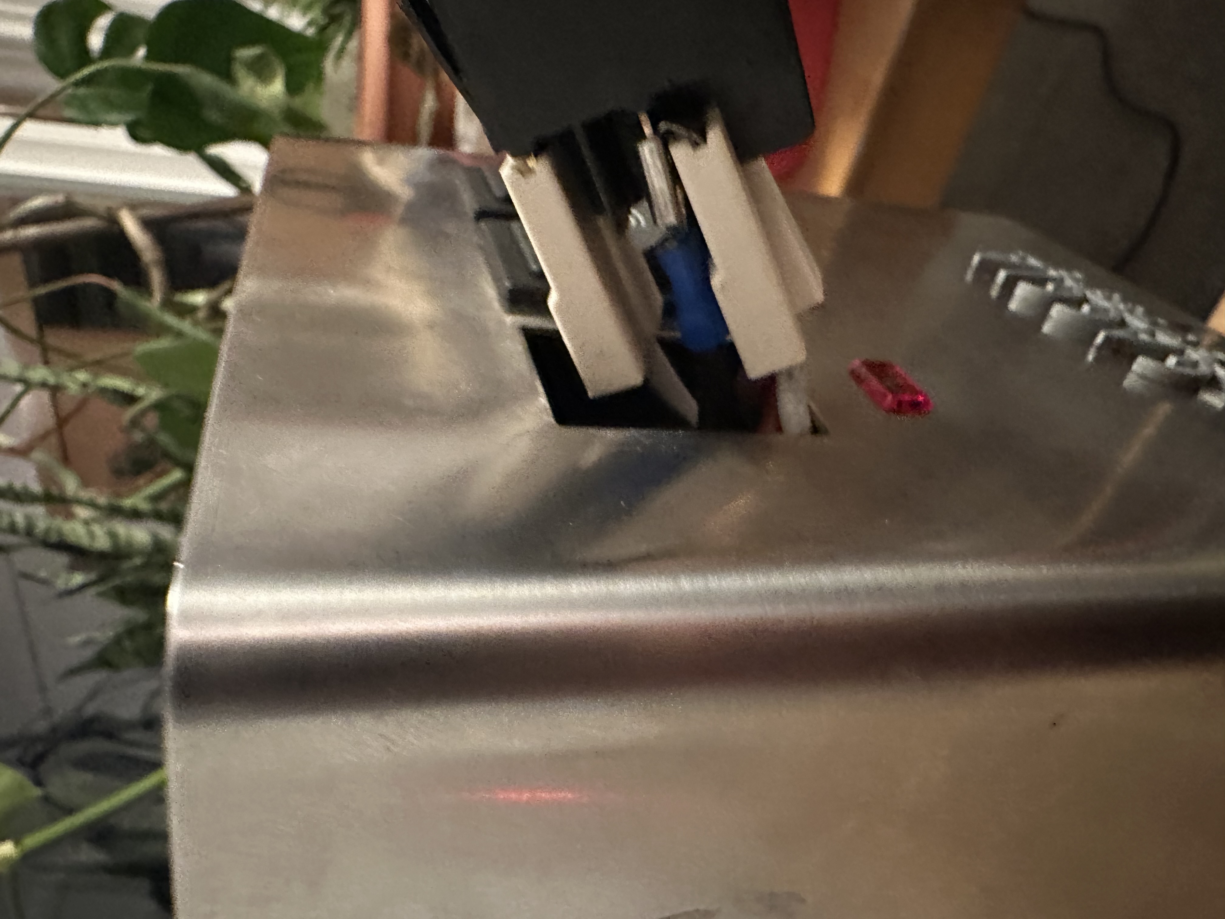
Most of these pictures were taken with a different power supply. I replaced the original with one that has more secure terminal connections.
Any Linux SBC should work about as well as another here. Likewise the software I wrote (which I’ll cover in a later post!) uses the Linux IndustrialIO driver subsystem, so a wide variety of common temperature sensors should be easy to support.
Replace the Thermostat
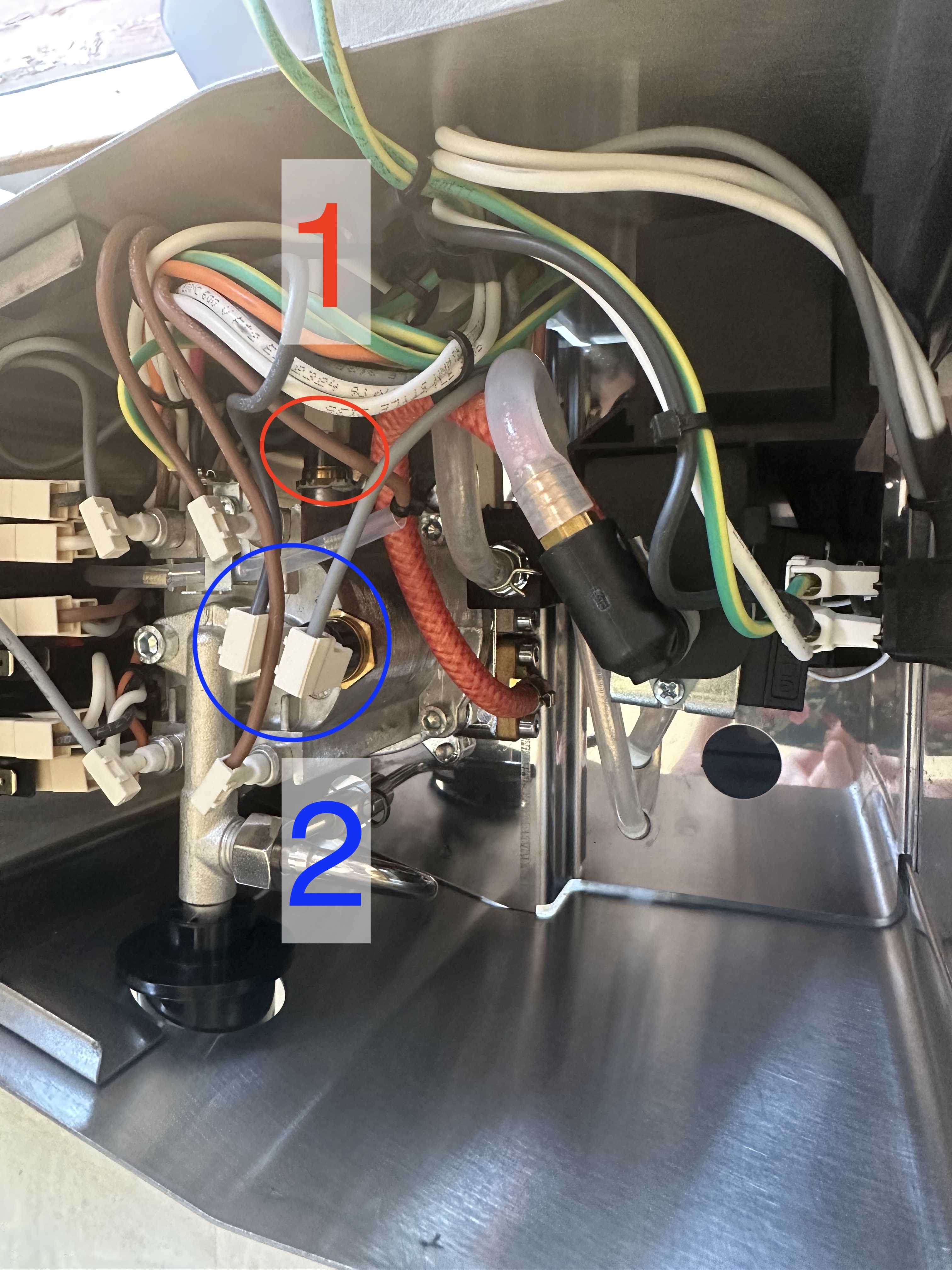
Here’s the inside of our espresso machine:
- The boiler thermostat (1) is on the side of the boiler, and can be difficult to access.
- The steam thermostat (2) is not modified, but may be useful to inspect.
Closing the main power switch allows electricity to reach the thermostat. The thermostat is a temperature activated switch. When the temperature is below 99c, the switch closes, powering the resistive heating element in the boiler. When the temperature rises above 115c, the switch opens, cutting power to the boiler.
We’re going to replace the thermostat with a sensor our controller can read. We’ll use a relay controlled by a GPIO on our controller to switch power to the boiler.
- Cut two 6” 14 gauge wires
- Terminate one end of each wire with a male spade connector
- Terminate the other end of each wire with a fork connector
- Connect the spade ends of the wires to the red and white wires currently attached to the thermostat
- Connect the fork ends of the wires to the relay output terminals
- Tuck the relay near the back of the machine
- Unscrew the thermostat
- Screw in the M4 threaded type K thermocouple
Some guides suggest using screws to mount the relay to the chassis for better heat dissipation. I didn’t bother with new thermal paste on the thermocouple, in part because I wasn’t certain whether the original was a special food safe compound.
Connect the controller
- Cut two 12” 22 gauge wires
- Terminate one end of each wire with a fork connector
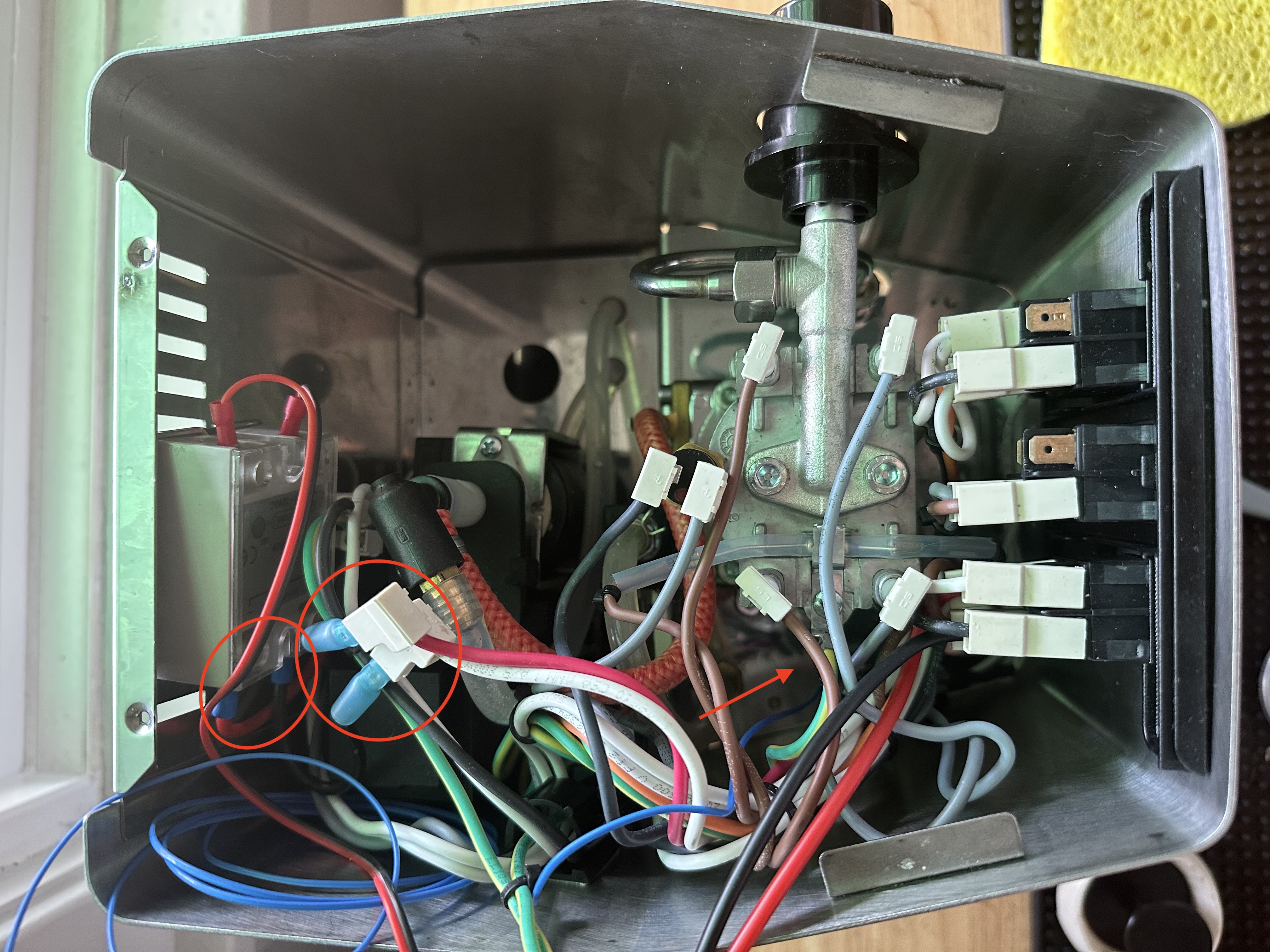
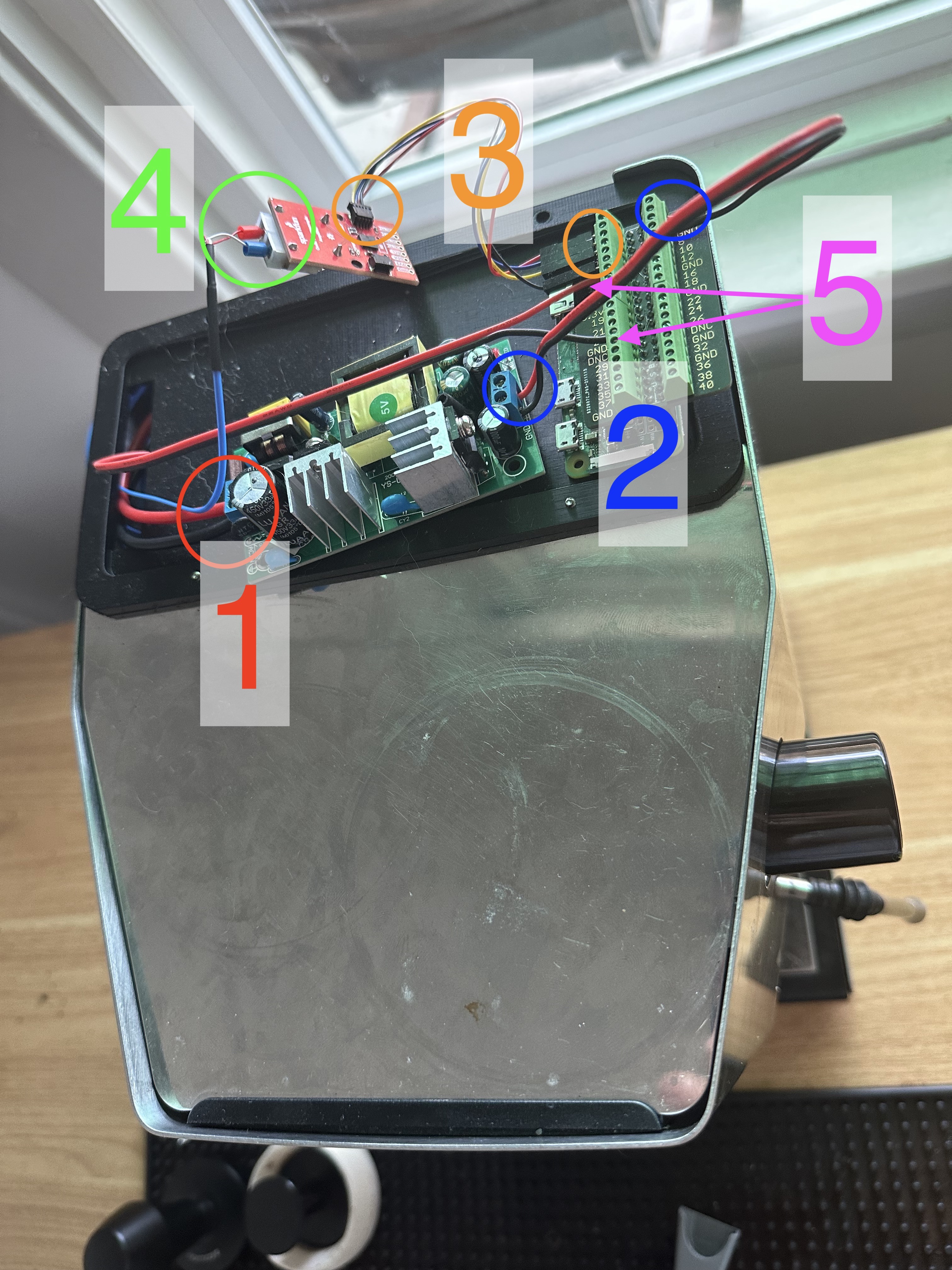
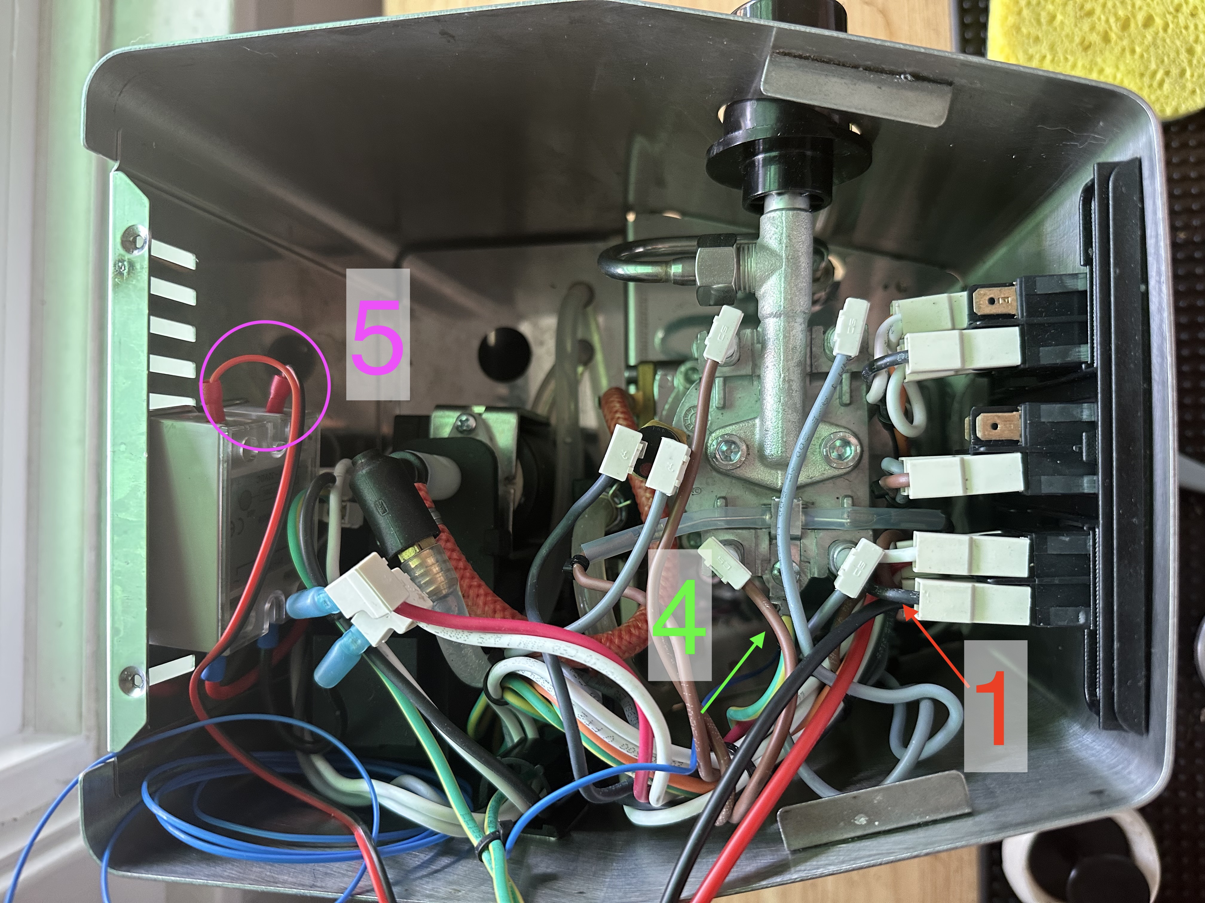
- (5, internal) Connect the forks to the control side of the relay
- (5, external) Connect the wires to a Pi GPIO and ground
- (4, external) Connect the thermocouple leads to the MCP9600 breakout
- (3, external) Connect the MCP9600 breakout to the Pi SDA, SCL, 3.3v, and ground
Connect the power supply
- Cut two 12” 14 gauge wires
- Terminate one end of each wire with a piggyback spade connector
- (1, internal) Remove the female spades from the bottom terminals on the main power switch
- Connect the female spades to the piggyback spades
- Connect the piggyback spades to the bottom terminals of the main power switch
- (1, external) Connect the wires to the power supply input
- Cut two 6” 22 gauge wires
- (2, external) Connect the power supply output to the Pi 5v and ground
It is critically important that all connections are secure.
What’s next?
In the next post, I’ll discuss generating a custom embedded Linux SD card image for our controller.